Additional Key Words: GIS, mine reclamation, terrain modeling
Technical Division: International Tailings Reclamation
Introduction
ArcView GIS (ESRI, 1996a), with the addition of the 3D Analyst extension (ESRI, 1997) provide a powerful suite of tools for terrain modeling and analysis.These tools include the ability to build terrain models from readily available electronic data (such as AutoCad files), query and analyze terrain data for characteristics such as slope and aspect, perform cut and fill calculations, and manipulate terrain models.The combination of terrain modeling and GIS functionality allow, for example, one to identify all areas at a mine that are greater than a particular slope using a database query.In this way, for example, one can rapidly identify areas of a large property that will need reclamation to meet regulatory requirements for post-mining land use.In addition, the 3D Analyst extension has the ability to render three-dimensional visualizations of terrain models, so that potential post-mining land use scenarios can be communicated to regulators and the public.A basic primer on terrain modeling has been presented in Price (1999).
The scripts described here have been developed to extend the capabilities of 3D Analyst to allow an automated approach to regrading complex features. The advantage of performing this work within a GIS package rather than a Cad-type package is that the GIS allows a variety of analyses to be performed once terrain models have been developed.In addition, the calculations described here are much more than just simple cut and fill calculations. The scripts described here have been developed specifically to allow realistic conceptual regrading of complex features.
The primary advantage of the method proposed here is that it allows detailed regrading of very complex features based on actual topography data.The scripts allow the user to define the geometry of the regrading based on the present-day topography, which most closely mimics how an actual earth-moving operation would proceed.That is, the starting locations for cut and fill are based on, and optimized to, actual topography.The methodology is also easy to use since the user needs only to identify a line on the ground, which follows actual topography, and the scripts will then create the desired slope based on that line, and perform cut and fill calculations.An additional advantage, as presented above, is that since the terrain modeling is done within GIS, a variety of querying and analysis tools are available to analyze the resulting conceptual topography.
New scripts developed using the Avenue (ERSI, 1996b) programming language for ArcView GIS 3.2 (ESRI, 1996a), and utilizing the 3D Analyst extension (ESRI, 1997), have been applied at several open-pit copper mines in the Southwest to evaluate stockpile regrading scenarios.Each mine site is faced with evaluating reclamation of waste-rock stockpiles from both a technical practicality and cost standpoint.The existing stockpiles have sideslopes in the range of 1.5:1 or steeper and can be several hundred feet high or more.State regulators were interested in evaluating the possibility of regrading the existing stockpiles to a 4:1 slope in an attempt to use traditional reclamation methods such as soil cover with revegetation.A GIS was used to develop a terrain model from existing electronic topography data available from AutoCad drawings. The terrain model was manipulated to create resulting topography that would result from regrading each stockpile.Calculations performed automatically by the scripts were used to balance cut and fill volumes such that cut and fill were optimized to be approximately equal.That is, material was removed from the upper portion of each stockpile and redistributed along the lower portion of the stockpile to decrease the sideslope from 1.5:1 to 4:1.
Conceptual regrading of stockpiles allows assessment of proposed reclamation schemes by evaluating issues such as volume of material moved and the new footprint of the regraded feature.Estimates of cut and fill volumes allow consideration of cost issues for regrading, while evaluation of revised stockpile footprints allows assessment of the effect of regrading on features near the present perimeter of the existing stockpile.The conceptual regrading is especially useful in evaluating the potential increase in the footprint of a stockpile after regrading.For example, a stockpile that is regraded from 1.5:1 to 4:1 will have a much larger footprint after regrading, since the stockpile has been spread out substantially in order to redistribute material originally at a 1.5:1 slope to a 4:1 slope. In many cases, features proximal to a stockpile - such as buildings, roads, surface-water features, and tanks - may be inundated if the stockpile were to be regraded.
The methods discussed here are presented primarily as they apply to waste-rock stockpiles at hard-rock mines in the Southwest.However, these same methodologies can be applied to other types of mines, such as coalmines, as well as to construction and earth-moving problems in general.
Methodology
Figure 1 presents a two-dimensional representation of the regrading
process.A cross section of an existing hypothetical stockpile with a slope
of 1.5:1 is shown.In order to balance cut and fill volumes, an iterative
process is used to select the excavation hinge line.The excavation
hinge line is defined as the line above which material is removed from
the stockpile to create the new slope (in this case, 4:1), and below which
material is added to create the new slope.The elevation of the excavation
hinge line can be constant, or vary across the stockpile.
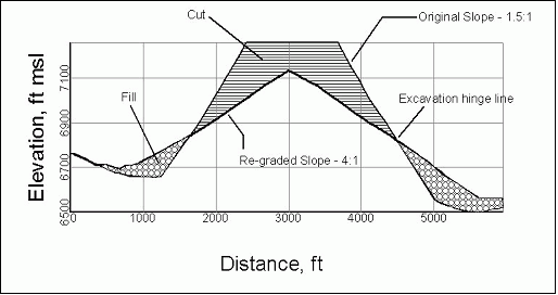
Figure 1.Cross-sectional view showing original
and regraded topography of a stockpile
In this example, we are assuming a constant-elevation hinge line.
For a stockpile with a relatively regular geometry, such as a truncated
cone, a constant-elevation hinge line works well.For stockpiles
with more complicated geometries, such as a stockpile built against a hillside,
typically a line of varying elevation must be used to define the excavation
hinge line.A trial-and-error approach must be used to define the
excavation hinge line such that the cut volume balances with the fill volume.
That is, a hinge line must be selected based on judgement, then the stockpile
is regraded by removing material above the hinge line and redistributing
it below the hinge line.Then the amount of material removed from
above the hinge line (the cut volume) is compared to the amount of material
added below the hinge line (the fill volume), to see if they match.
The cut and fill volumes should balance so that if the regrading were actually
completed in the field, the least amount of material would be moved, thus
reducing earthmoving.
The first step in the regrading process is to build an accurate
terrain model of present-day topography for a particular stockpile.
In the case of this study, this was done using existing electronic data,
in the form of AutoCad files.In order to build a terrain model,
the only condition is that the contour lines in the electronic file must
have elevations assigned to them, so that a three-dimensional surface can
be built from them.This is typically the case for topography data
used for mine-planning purposes.ArcView GIS, with the addition of
the 3D Analyst extension, uses a triangulated irregular network (TIN)
to represent three-dimensional surfaces.The TIN represents the surface
using contiguous, non-overlapping triangular faces, with a height value
for each triangle node, and preserves all observed data points.Figures
2 and 3 show examples of raw topography and the resulting TIN, respectively.
Once a TIN of topography has been constructed, the conceptual regrading
process can be performed.As discussed above, the first step in the
regrading process is to select the excavation hinge line that allows cut
and fill volumes to balance.This is an iterative, trial-and-error
process by which an analyst must select a starting excavation hinge line,
then calculate the cut and fill volumes associated with that particular
hinge line.The cut volume is calculated by removing material to
reach the desired slope above line hinge line (Figure 1), and the fill
volume is calculated by filling in below the line to reach the desired
slope (Figure 1).For the regrading performed as part of this study,
an initial hinge line was selected for each stockpile based on judgement,
and the automated scripts were used to calculated the resulting cut and
fill volumes.The location of the hinge line was then adjusted in
order to approximately balance the cut and fill volumes.This process
typically took several tries.
The approach for manipulating the TIN to develop the regraded surface is conceptually straightforward,
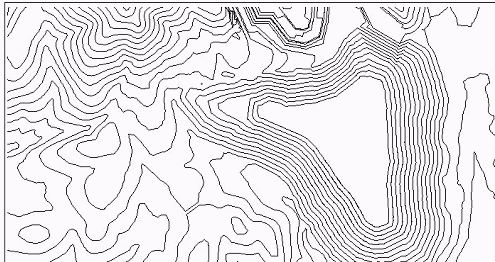
Figure 2.Raw topography data used to build
a TIN
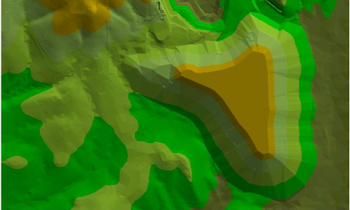
Figure 3.Three-dimensional visualization of
TIN built from topography data shown in Figure 2
but complex to implement from a programming perspective.Each
of these steps is performed in an automated fashion, but they are discussed
here by breaking the process down into its component steps.
The process of removing material above the excavation hinge line (the cut calculation) will be discussed first.The fill process will be discussed second.
Because the algorithm is based upon using sequential buffers to build the desired slope, the excavation hinge line must be defined as a closed polygon of a known elevation.The hinge line can either have a constant elevation (such as a contour around the perimeter of a stockpile), or the elevation can vary along its perimeter.Once the hinge line is defined, a series of new contour lines that will define the regraded surface are developed by stepping inward and upward from the hinge line at a user-defined step interval.This was accomplished in Avenue in one of two ways.For a constant-elevation hinge line, a simple buffering scheme was used to step in from the hinge line.For a varying-elevation hinge line, an elevation-dependant, variable-width buffering scheme was used to step in from the hinge line.
For example, for a 4:1 slope, if the hinge line is a closed polygon at an elevation of 5100 feet, and the user has defined the step interval as 100 feet, then a new polygon is created at an elevation of 5200 feet that is inside the hinge line and is 400 feet from it at all points along its perimeter (Figure 4).This type of polygon is also called a buffer. A surface defined by these two polygons will have a 4:1 slope.This process is repeated at successive intervals up the height of the existing stockpile.If the slope of a stockpile is decreased, the elevation of the resulting regraded stockpile will always be lower than the original stockpile.
Once a series of polygons and their elevations has been created, the script generates a TIN from the polygons (the regraded surface). A cut/fill calculation is then performed by subtracting the regraded surface from the existing surface, and determining the amount of material that must be removed to regrade to the desired slope.The cut volume can then be compared with the fill volume to check for mass balance. If the final location of the excavation hinge line has been determined, the existing surface inside the hinge line boundary is replaced by the regraded surface.This is performed by clipping out a portion of the existing topography TIN and replacing it with the corresponding clipped portion of the proposed topography TIN.
The fill calculation proceeds in a fashion similar to the cut
calculation.Starting at the excavation hinge line, a series of polygons
is generated by stepping out and down from the hinge line.To use
the example
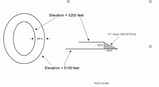
Figure 4.Schematic diagram of the process for
creating constant-slope feature
given above, if the hinge line is a closed polygon at 5100 feet (Figure
4), to create a 4:1 slope, a buffer is created that is at an elevation
of 5000 feet and is at all points 400 feet outside the perimeter of the
hinge line.This continues in a stepwise fashion until the lowest
elevation on the existing surface is reached.
The existing surface must then be replaced by the regraded surface in those areas where it is appropriate.This is accomplished in two steps.First, a cut/fill calculation is performed between the existing surface and the proposed (regraded) surface.The cut/fill calculation will define an area of fill where the proposed surface is above the existing surface.That is, a standard cut/fill calculation will show that where a proposed surface is above an existing surface, material must be added (fill) to the existing surface to bring it up to the level of the proposed surface.The outer boundary of the fill area defines a polygon that indicates the area of the existing topography that will be replaced by the proposed topography.
In the second step, the portion of the existing topography that is contained within the fill area is removed and replaced by the proposed topography.This is done by clipping an area of the existing topography TIN and inserting the corresponding clipped portion of the proposed topography TIN.The two TINs are then combined to create a single TIN, as described above.
For the fill calculation, the user may mask off certain areas that are not allowed to be filled.For example, if a stockpile were adjacent to an open-pit mine, one could mask off the mine excavation area so that it would not be filled during the conceptual regrading process. This allows the user to evaluate various regrading scenarios.
Results and Discussions
Example Regrading
Figures 5 and 6 present existing and regraded topography, respectively, for a hypothetical stockpile.The existing slope of the stockpile is 1.5:1, or about 30 degrees.Figure 5 shows the placement of the excavation hinge line.As discussed above, the location of this line is determined by balancing cut and fill volumes to the most accurate extent possible.Figure 6 presents the results of the conceptual regrading of the stockpile to a 4:1 slope, or about 14 degrees.The figure also presents the locations of the footprints of both the original stockpile and the regraded stockpile.Note that the area of the footprint of the stockpile has increased substantially due to material being removed from the top of the stockpile and added to the bottom perimeter in order to reconfigure the stockpile slope to the desired 4:1 slope.
In addition to estimating cut and fill volumes, the ability to evaluate the revised footprint of the regraded stockpile is a powerful tool in evaluating the technical practicability of a potential regrading operation. For example, knowing that a group of buildings or a stream channel would become inundated during a particular regrading scenario is an important factor for planning purposes.
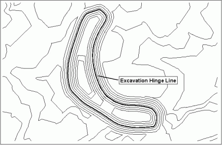
Figure 5.Original topography for a hypothetical
stockpile showing excavation hinge line
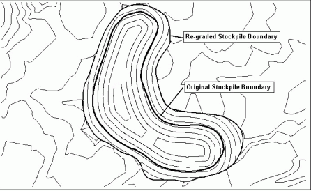
Figure 6.Regraded stockpile showing topography,
original footprint, and revised footprint
This methodology was applied to a number of open-pit copper mine
sites in the Southwest, with similar results at each site: the volume of
material that would have to be moved to regrade all stockpiles to 4:1 is
quite large and would be very expensive and time-consuming to move.
However, there has been no real agreement as to whether or not this sort
of regrading plan is technically practical at this time.However,
the tools described here have been helpful in at least estimating the volume
of stockpile material that would have to be moved in order to reclaim these
areas.Therefore, these tools have been helpful in opening a dialog
with regulators and giving all parties some sense of what may be involved
in returning mined areas to a configuration that may allow reclamation
once the mine closes.
Developing Input for a Geochemical Mass-Loading Model
A terrain model of the proposed topography can be used to develop isopach maps of stockpile thickness, which are then input into a geochemical mass-loading model used to evaluate potential mass loading from the regraded stockpile.Input to the geochemical model is a series of thickness bins, or a histogram of material thicknesses.These are developed from the GIS by discretizing a grid of points onto the stockpile and then at each point subtracting proposed topography from pre-mining topography to calculate stockpile thickness at each point.Thickness calculations can be performed for existing as well as proposed stockpiles, thus allowing a comparison of mass loading rates to underlying groundwater with existing versus proposed topography.The methods used to link the GIS calculations to a geochemical model are discussed in Earley et al.(2001) and will not be presented in detail here.
Conclusions
Three-dimensional GIS is a powerful tool for planning and costing purposes when evaluating regrading scenarios.Existing data in electronic format can be used to develop terrain models (TINs) of existing topography, which can then be manipulated to evaluate various regrading scenarios. The scripts described here can be used to rapidly and effectively evaluate a variety of regrading scenarios in terms of volume of material that must be moved, excavation and hauling costs, and degree of technical practicability. In addition, the GIS provides important input data for geochemical models used to evaluate mass loading from existing versus proposed stockpile configurations. Results of the geochemical modeling indicated that regrading and reclaiming of stockpiles did not substantially reduce the potential mass loading to the underlying aquifer(s).Likewise, while the methods presented here were helpful in estimating earthmoving volumes and costs, there is no agreement yet on the technical practicality of attempting to perform the regrading.
Three-dimensional visualizations of both existing and proposed topography, as well as surface features, can also be developed using the 3D Analyst extension for ArcView.These can be powerful visual tools for communicating with management, regulators, and the public.By using three-dimensional visualizations, it is possible to view the outcome of a potential regrading scenario and communicate that to a non-technical audience.
Literature Cited
ESRI, 1996a.Using ArcView GIS, the geographic information system for everyone.Environmental Systems Research Institute, Inc.
ESRI, 1996b.Using Avenue, customization and application development for ArcView GIS.Environmental Systems Research Institute, Inc.
ESRI, 1997.Using ArcView 3D Analyst, 3D surface creation, visualization, and analysis.Environmental Systems Research Institute, Inc.
Earley, et al.2001.GIS-facilitated, hydrogeochemical modeling for mine waste reclamations.p.273-282.In Tailings and mine waste '01, Proceedings of the eighth international conference on tailings and mine waste '01, 16-19 January 2001.A.A.Balkema, Rotterdam/Brookfield.
Price, M.1999.Terrain modeling with ArcView 3D Analyst.ESRI ArcUser
Magazine, Jan-March 1999.http://www.esri.com/news/arcuser/0199/
web4.html.