In recent years regional and local governments in Italy
have committed to long-term projects for creating and maintaining an
integrated geospatial information repository from regional and local
administrations' information systems. SIGMATER is one such project. Its
primary goal is facilitating multiple eGovernance initiatives for
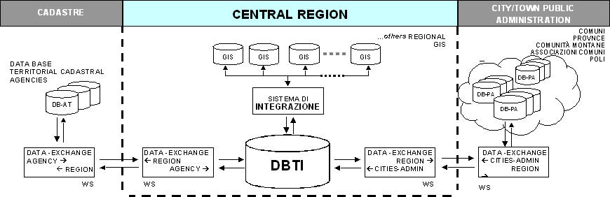
enhanced, efficient citizen services. Central to this effort is
effective geospatial data exchange between cooperating regional and
local public administrations, as outlined in the following diagram.
The primary benefit is a consistent, up-to-date geospatial database
that supports local and regional authorities in building and delivering
Web applications for tax assessment, permitting, registrations, city
planning, environmental impact analysis, infrastructure planning, use
of public facilities, and so on.
The fundamental technical requirement is a semi-automated workflow that enables bi-directional geospatial information exchange between the central, regional and local information systems. The project's sponsors were particularly insistent on the use of open and standard technologies - such as SQL, J2EE, and XML - and geospatial industry standards adopted by OGC, ISO TC211, EU's INSPIRE and Italy's Intesa GIS.
Presently, two key objectives of the overall project have been implemented:
This article describes a Web services-based approach to addressing the above issue. The solution presented here is based on ABACO's interactive Web-based GIS toolkit, DbMAP ASJ, and the persistent topology storage model in Oracle Spatial 10g Release 2. We start by briefly describing the DbMap ASJ suite and the Oracle Spatial 10g Topology Model. Next we outline the Bolzano DBTI project requirements, its architecture, and the ABACO-Oracle implementation. Finally we conclude with a brief discussion of lessons learned from the project.
ABACO DbMAP ASJ
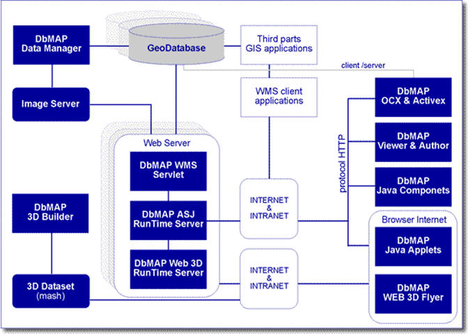
The DbMAP ASJ suite is a toolkit for the development and deployment of Web GIS applications. It has a simple and scalable architecture that assures the best interoperability among applications and data. DbMAP ASJ takes advantage of all the features, flexibility, reliability and scalability of Oracle Locator and Spatial.
It works with any Application Server and J2EE Container (Oracle, TOMCAT, IBM WEBSPHERE, etc.), and runs on Windows, Linux and MAC OS. It offers Web map services, supported by any client WMS, and Servlet services accessible with advanced royalty-free applets, OCX and Java, or even open source components. These components are exploitable in Web GIS applications developed with the same programming tools already used for traditional applications in Web browsers, and desktop, hand-held or pocket PCs. The figure above depicts how a Web GIS solution may be developed and deployed using the DbMAP ASJ Suite.
Overview of the Oracle 10g Topology model
A topological data model is a means of structuring and storing data such that containment, adjacency and connectivity relationships between spatial entities are pre-computed and persistently managed. Such a model has several benefits including elimination of redundancies in storage, simpler implementation of spatial integrity constraints or business rules, and efficient management of spatial hierarchies. The topological model consists of a set of topological primitives (nodes, edges and faces), and relationships between them and geographic features, as shown in the following figure.
The Oracle Spatial topology data model lets you work with data about
nodes, edges and faces in a topology. For example, US Census geographic
data is provided in terms of nodes, chains and polygons, and this data
can be represented using the topology data model. You can store
information about topological elements and geometry layers in Oracle
Spatial tables and metadata views. You can then perform certain spatial
operations referencing the topological elements, for example, finding
which chains (such as streets) have any spatial interaction with a
specific polygon entity (such as a park).
The basic elements, or primitives, in a topology are nodes, edges and faces. A point represents a node. Two nodes, its start and end, bound an edge and the order of these nodes gives the edge a direction. A face, represented by a polygon, contains reference to one directed edge on its boundary.
Any persistent topology management solution must provide five basic features.
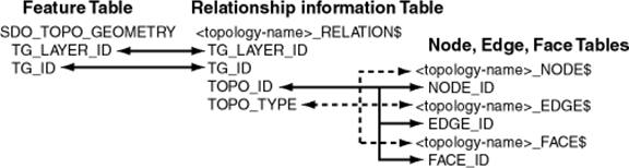
Each feature is defined as an object of type SDO_TOPO_GEOMETRY which identifies the topology geometry type and the IDs for the topology geometry and topology. All primitives in a topology are stored in tables named using the convention _NODE$, _EDGE$, _FACE$. A table named _RELATION$ stores the mapping between the spatial feature and its topological primitives. The following figure depicts this relationship between the features and a topology.
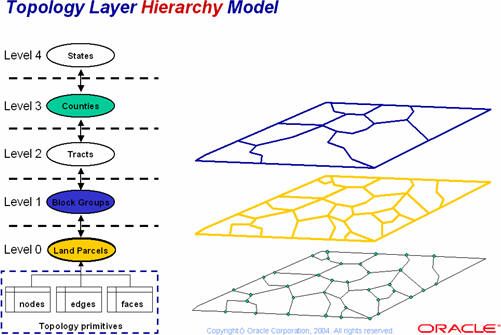
In some topologies, the topology geometry layers (feature layers) have one or more parent-child relationships in a topology hierarchy. That is, the layer at the topmost level consists of features in its child layer at the next level down in the hierarchy; the child layer might consist of features in its child layer at the next layer farther down, and so on.
If the topology geometry layers in a topology have this hierarchical relationship, it is far more efficient to model the layers as hierarchical than if you specify all topology geometry layers at a single level (that is, with no hierarchy). For example, it is more efficient to construct SDO_TOPO_GEOMETRY objects for counties by specifying only the tracts in the county than by specifying all land parcels in all block groups in all tracts in the county.
The lowest level (for the topology geometry layer containing the smallest kinds of features) in a hierarchy is level 0, and successive higher levels are numbered 1, 2, and so on. Topology geometry layers at adjacent levels of a hierarchy have a parent-child relationship. Each topology geometry layer at the higher level is the parent layer for one layer at the lower level, which is its child layer. A parent layer can have only one child layer, but a child layer can have one or more parent layers.
The Oracle Spatial topology data model implementation provides several PL/SQL functions and packages for querying features tables, navigational operations, updating a topology and maintaining integrity rules and feature mappings on updates, feature level updates, and building feature geometry. Feature tables are queried using spatial operators such as SDO_ANYINTERACT, SDO_CONTAINS, SDO_TOUCH, or SDO_OVERLAP. Topology creation and maintenance functionality is provided in the SDO_TOPO package. The key procedures discussed in this article are CREATE_TOPOLOGY and ADD_GEOMETRY_LAYER. The SDO_TOPO_MAP PL/SQL package, and corresponding sdo_topo Java library, provide all the navigation and editing functions and procedures such as GET_CONTAINING_FACE, GET_EDGE_NODES, ADD_NODE, ADD_EDGE, CREATE_FEATURE, or ADD_POLYGON_GEOMETRY. All data and spatial integrity rules are defined using triggers since ours is an SQL implementation. Since the feature to topology primitive mapping is stored in the RELATION table, most of these integrity rules can be defined as triggers on the RELATION table.
Having outlined the logical and physical design of the Oracle Spatial topology data model, we now describe how it is used in the DBTI update prototype.
Requirements and Implementation of an Integrated Topographic Database
The administrative hierarchy in Italy consists of regions, provinces and towns. Towns create and maintain the most granular layer of topography, known as Cartografia Numerica (the City Technical Cartography composed of topographic primitives), which is made up of multiple tables of topographic information.
The fundamental application requirement is a semi-automated workflow that enables bi-directional geospatial information exchange between the central, regional and local information systems. Towns cooperate with each other in providing services, and hence require up-to-date and accurate geospatial information for the province or region containing the towns.
The data requirements for the DBTI prototype project are summarized below.
The project's sponsors were particularly insistent on
the use of open
and standard technologies - such as SQL, J2EE and XML - and geospatial
industry standards adopted by OGC, ISO TC211, EU's INSPIRE, and Italy's
Intesa GIS TopographicDB Specification.
To satisfy these requirements, Oracle Italia built upon a successful experience in two 'national scale' projects: SIGMATER and WEGIS. SIGMATER is an eGovernance project that facilitates collaboration and cooperation between central, regional and local public administrations. The project's main objective is the interoperation between regional and cadastral agencies and between regions and towns. One aspect of the overall project was the creation and maintenance of a DBTI. Web services were to be used for the geospatial data exchange between the various agencies.
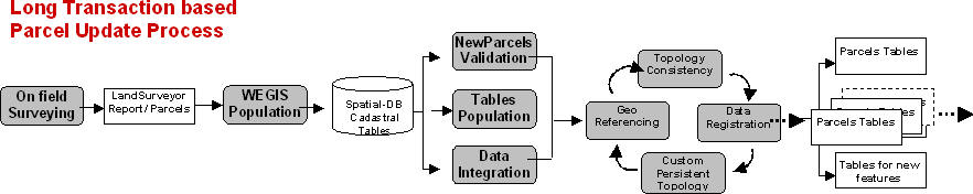
WEGIS is the project implemented by SOGEI for the Italian Land Agency, in order to manage cadastral maps distributed over a hundred regional and local territorial agency systems. Updates are managed via a long transaction process (shown in the figure below) whereby changes are submitted, validated, approved and finally posted to the central repository.
Updates to the DBTI had to be managed and propagated using the WEGIS
workflow and orchestrated in a SIGMATER-like system architecture. This
calls for a central database (DBTI) that is kept up-to-date using a Web
services-based workflow that incorporates changes from the towns and
provinces.
An essential element, and success factor in this process, is the definition, creation, and consistent use of a persistent, unique identifier for each topographic object. The UK Ordnance Survey (OS) pioneered this approach and it uses Topographic Object Identifiers (TOIDs) in its MasterMap line of products. The TOIDs are a basic means to enable an automated exchange of data updates between the OS and its customers. The DBTI project adopted a similar approach.
Using TOIDs enabled a simplified and semi-automatic workflow to incorporate changes made by towns into the central database. The topographic objects to be introduced into the central database go through a validation and impact analysis process before being committed, or routed for further manual verification, editing and approval. So all new objects are inserted into a table named NEW_OF and then subjected to the validation workflow.
The automated workflow consists of IMPACT, CREATION and COMMIT phases, while the semi-automated workflow that involves interactive editing and approvals consists of IMPACT, SPLITTING, EDITING and COMMIT phases. These are explained in further detail below.
The NEW_OF table contains an ID, polygon geometry, layer type (e.g. green areas or streets), session ID, and other attribute fields. The ID is the same as a TOID, and the session ID simply identifies a specific update request. Each update request is evaluated and then processed either automatically or interactively.
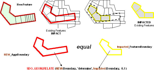
The first step is an IMPACT analysis on existing features that is processed as follows. The new feature may consist of one or more polygons, or faces, all referenced using the same session ID. The first step is to create a bounding polygon (NewFeatureBoundary) of the new feature if it is made up of multiple polygons. Next this boundary is used to query the persistent topology, i.e. the topographic tables, to determine the objects that are covered by it. Then a new geometry (ImpactedFeaturesBoundary), i.e. the existing feature's boundary, is created using the same SDO_AGGR_UNION() function as was done for new features.
These two geometries are then compared to determine if the NewFeatureBoundary is equal to, covers, or intersects the ImpactedFeaturesBoundary. If the two boundaries are equal, then the automated creation and commit steps are performed. If the two boundaries are non-equal then the interactive update process is followed.
Creation of new features involves converting the SDO_GEOMETRY based
representation of the new feature to an SDO_TOPO_GEOMETRY
representation using topological primitives and then creating a
geometry feature with the SDO_TOPO_MAP.CREATE_FEATURE() procedure,
which inserts the topological primitives and adds an entry in the
RELATION table. The new feature may be added at the base, or a higher
level of the topology hierarchy defined in the DBTI schema.
Once the new feature has been created, the changes are COMMITTED to the database. This involves deleting all primitives that make up the ExistingFeaturesBoundary and replacing them with the ones added for the new feature. A consistency check then identifies, and deletes, any primitives not referenced by features. This ensures a clean and a consistent topology that is the level 0 in the defined feature hierarchy.
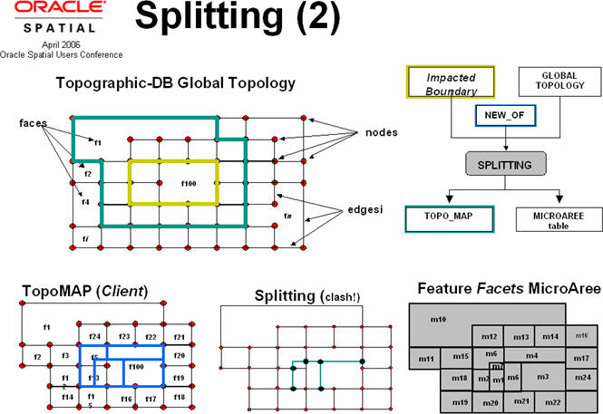
If the NewFeatureBoundary and ExistingFeaturesBoundary are non-equal, then the interactive process is followed. The first step is SPLITTING, followed by EDITING, and then a COMMIT.
The SPLITTING step uses the ADD_POLYGON_GEOMETRY procedure to create a new topology from the new and existing features. That is, it splits the new and existing features into facets. A MicroAreas feature table references these facets and becomes the input to the EDITING process.
Once MicroAreas have been generated, what's needed is a graphic interface like AbacoSuite to select split MicroAreas and a PL/SQL stored procedure to compose them in new (topo) features by invoking appropriate SQL functions. This procedure called InsertUpdateTopology, receives the following input: topographic layer ID, list of select MicroAreas, TOID and various attributes. It in turn invokes the relevant topology checking and creation functions of the Oracle 10g Topology model, and once all updates and validation are done, it commits the changes to the database.
The above process is then repeated for each of the entries in the NEW_OF table until all are processed.
Discussion
The Comune di Bolzano successfully implemented the pilot project to assess the feasibility and effectiveness of a semi-automated approach to updating a land registry's topographic database. Professional land surveyors could continue to use their preferred tools and file formats, such as DWG or SHP, and exchange topographic and cadastral information with the municipal authority's system in a much more efficient and effective manner. Architect Franco Barducci, Director of Comune di Bolzano's Territorial Information Service, was particularly excited by how accuracy and consistency issues due to the lack of a structured topology model were overcome using Oracle 10g's persistent Topology Data Model. He was equally pleased that the new system leveraged all the benefits of an enterprise geospatial database and yet end users and stakeholders such as architects and land surveyors did not have to dramatically alter their current business workflows.
 |
The fundamental technical requirement is a semi-automated workflow that enables bi-directional geospatial information exchange between the central, regional and local information systems. The project's sponsors were particularly insistent on the use of open and standard technologies - such as SQL, J2EE, and XML - and geospatial industry standards adopted by OGC, ISO TC211, EU's INSPIRE and Italy's Intesa GIS.
Presently, two key objectives of the overall project have been implemented:
- the creation and maintenance of a central integrated geospatial database known as the Topographic DB (DBTI, or the integrated topographic database);
- implementation of Service Oriented Architecture (SOA) based processes for data exchange between the various agencies
This article describes a Web services-based approach to addressing the above issue. The solution presented here is based on ABACO's interactive Web-based GIS toolkit, DbMAP ASJ, and the persistent topology storage model in Oracle Spatial 10g Release 2. We start by briefly describing the DbMap ASJ suite and the Oracle Spatial 10g Topology Model. Next we outline the Bolzano DBTI project requirements, its architecture, and the ABACO-Oracle implementation. Finally we conclude with a brief discussion of lessons learned from the project.
ABACO DbMAP ASJ
The DbMAP ASJ suite is a toolkit for the development and deployment of Web GIS applications. It has a simple and scalable architecture that assures the best interoperability among applications and data. DbMAP ASJ takes advantage of all the features, flexibility, reliability and scalability of Oracle Locator and Spatial.
It works with any Application Server and J2EE Container (Oracle, TOMCAT, IBM WEBSPHERE, etc.), and runs on Windows, Linux and MAC OS. It offers Web map services, supported by any client WMS, and Servlet services accessible with advanced royalty-free applets, OCX and Java, or even open source components. These components are exploitable in Web GIS applications developed with the same programming tools already used for traditional applications in Web browsers, and desktop, hand-held or pocket PCs. The figure above depicts how a Web GIS solution may be developed and deployed using the DbMAP ASJ Suite.
 |
A topological data model is a means of structuring and storing data such that containment, adjacency and connectivity relationships between spatial entities are pre-computed and persistently managed. Such a model has several benefits including elimination of redundancies in storage, simpler implementation of spatial integrity constraints or business rules, and efficient management of spatial hierarchies. The topological model consists of a set of topological primitives (nodes, edges and faces), and relationships between them and geographic features, as shown in the following figure.
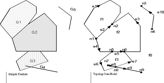 |
The basic elements, or primitives, in a topology are nodes, edges and faces. A point represents a node. Two nodes, its start and end, bound an edge and the order of these nodes gives the edge a direction. A face, represented by a polygon, contains reference to one directed edge on its boundary.
Any persistent topology management solution must provide five basic features.
- An open storage model for the topological primitives
- Efficient interfaces to define spatial features on existing topological primitives
- Efficient interfaces to edit topological primitives directly while maintaining the feature to primitive mappings
- Efficient means to perform spatial queries on the features
- Procedures for defining and evaluating validation rules on the topology
Each feature is defined as an object of type SDO_TOPO_GEOMETRY which identifies the topology geometry type and the IDs for the topology geometry and topology. All primitives in a topology are stored in tables named using the convention _NODE$, _EDGE$, _FACE$. A table named _RELATION$ stores the mapping between the spatial feature and its topological primitives. The following figure depicts this relationship between the features and a topology.
 |
In some topologies, the topology geometry layers (feature layers) have one or more parent-child relationships in a topology hierarchy. That is, the layer at the topmost level consists of features in its child layer at the next level down in the hierarchy; the child layer might consist of features in its child layer at the next layer farther down, and so on.
If the topology geometry layers in a topology have this hierarchical relationship, it is far more efficient to model the layers as hierarchical than if you specify all topology geometry layers at a single level (that is, with no hierarchy). For example, it is more efficient to construct SDO_TOPO_GEOMETRY objects for counties by specifying only the tracts in the county than by specifying all land parcels in all block groups in all tracts in the county.
The lowest level (for the topology geometry layer containing the smallest kinds of features) in a hierarchy is level 0, and successive higher levels are numbered 1, 2, and so on. Topology geometry layers at adjacent levels of a hierarchy have a parent-child relationship. Each topology geometry layer at the higher level is the parent layer for one layer at the lower level, which is its child layer. A parent layer can have only one child layer, but a child layer can have one or more parent layers.
The Oracle Spatial topology data model implementation provides several PL/SQL functions and packages for querying features tables, navigational operations, updating a topology and maintaining integrity rules and feature mappings on updates, feature level updates, and building feature geometry. Feature tables are queried using spatial operators such as SDO_ANYINTERACT, SDO_CONTAINS, SDO_TOUCH, or SDO_OVERLAP. Topology creation and maintenance functionality is provided in the SDO_TOPO package. The key procedures discussed in this article are CREATE_TOPOLOGY and ADD_GEOMETRY_LAYER. The SDO_TOPO_MAP PL/SQL package, and corresponding sdo_topo Java library, provide all the navigation and editing functions and procedures such as GET_CONTAINING_FACE, GET_EDGE_NODES, ADD_NODE, ADD_EDGE, CREATE_FEATURE, or ADD_POLYGON_GEOMETRY. All data and spatial integrity rules are defined using triggers since ours is an SQL implementation. Since the feature to topology primitive mapping is stored in the RELATION table, most of these integrity rules can be defined as triggers on the RELATION table.
Having outlined the logical and physical design of the Oracle Spatial topology data model, we now describe how it is used in the DBTI update prototype.
Requirements and Implementation of an Integrated Topographic Database
The administrative hierarchy in Italy consists of regions, provinces and towns. Towns create and maintain the most granular layer of topography, known as Cartografia Numerica (the City Technical Cartography composed of topographic primitives), which is made up of multiple tables of topographic information.
The fundamental application requirement is a semi-automated workflow that enables bi-directional geospatial information exchange between the central, regional and local information systems. Towns cooperate with each other in providing services, and hence require up-to-date and accurate geospatial information for the province or region containing the towns.
The data requirements for the DBTI prototype project are summarized below.
- Topographic features structured as a full planar partition (i.e. no overlaps or intersection allowed). This necessitates the use of a persistent topology data model.
- Basic topographic layers are: the Aree_Verdi (Green Areas), the Aree_Unit_Volumetriche (the minimum component of a building) and the Aree_Stradali (Street Areas). These are populated in specific spatial tables named Topographic Tables.
- Updated or new topographic features, which are stored in the table NEW_OF, which contains an ID, an OGC polygon geometry type, the type of granular layer, and a session_id that identifies the update request.
 |
To satisfy these requirements, Oracle Italia built upon a successful experience in two 'national scale' projects: SIGMATER and WEGIS. SIGMATER is an eGovernance project that facilitates collaboration and cooperation between central, regional and local public administrations. The project's main objective is the interoperation between regional and cadastral agencies and between regions and towns. One aspect of the overall project was the creation and maintenance of a DBTI. Web services were to be used for the geospatial data exchange between the various agencies.
WEGIS is the project implemented by SOGEI for the Italian Land Agency, in order to manage cadastral maps distributed over a hundred regional and local territorial agency systems. Updates are managed via a long transaction process (shown in the figure below) whereby changes are submitted, validated, approved and finally posted to the central repository.
 |
An essential element, and success factor in this process, is the definition, creation, and consistent use of a persistent, unique identifier for each topographic object. The UK Ordnance Survey (OS) pioneered this approach and it uses Topographic Object Identifiers (TOIDs) in its MasterMap line of products. The TOIDs are a basic means to enable an automated exchange of data updates between the OS and its customers. The DBTI project adopted a similar approach.
Using TOIDs enabled a simplified and semi-automatic workflow to incorporate changes made by towns into the central database. The topographic objects to be introduced into the central database go through a validation and impact analysis process before being committed, or routed for further manual verification, editing and approval. So all new objects are inserted into a table named NEW_OF and then subjected to the validation workflow.
The automated workflow consists of IMPACT, CREATION and COMMIT phases, while the semi-automated workflow that involves interactive editing and approvals consists of IMPACT, SPLITTING, EDITING and COMMIT phases. These are explained in further detail below.
 |
 |
The NEW_OF table contains an ID, polygon geometry, layer type (e.g. green areas or streets), session ID, and other attribute fields. The ID is the same as a TOID, and the session ID simply identifies a specific update request. Each update request is evaluated and then processed either automatically or interactively.
The first step is an IMPACT analysis on existing features that is processed as follows. The new feature may consist of one or more polygons, or faces, all referenced using the same session ID. The first step is to create a bounding polygon (NewFeatureBoundary) of the new feature if it is made up of multiple polygons. Next this boundary is used to query the persistent topology, i.e. the topographic tables, to determine the objects that are covered by it. Then a new geometry (ImpactedFeaturesBoundary), i.e. the existing feature's boundary, is created using the same SDO_AGGR_UNION() function as was done for new features.
These two geometries are then compared to determine if the NewFeatureBoundary is equal to, covers, or intersects the ImpactedFeaturesBoundary. If the two boundaries are equal, then the automated creation and commit steps are performed. If the two boundaries are non-equal then the interactive update process is followed.
 |
Once the new feature has been created, the changes are COMMITTED to the database. This involves deleting all primitives that make up the ExistingFeaturesBoundary and replacing them with the ones added for the new feature. A consistency check then identifies, and deletes, any primitives not referenced by features. This ensures a clean and a consistent topology that is the level 0 in the defined feature hierarchy.
If the NewFeatureBoundary and ExistingFeaturesBoundary are non-equal, then the interactive process is followed. The first step is SPLITTING, followed by EDITING, and then a COMMIT.
The SPLITTING step uses the ADD_POLYGON_GEOMETRY procedure to create a new topology from the new and existing features. That is, it splits the new and existing features into facets. A MicroAreas feature table references these facets and becomes the input to the EDITING process.
Once MicroAreas have been generated, what's needed is a graphic interface like AbacoSuite to select split MicroAreas and a PL/SQL stored procedure to compose them in new (topo) features by invoking appropriate SQL functions. This procedure called InsertUpdateTopology, receives the following input: topographic layer ID, list of select MicroAreas, TOID and various attributes. It in turn invokes the relevant topology checking and creation functions of the Oracle 10g Topology model, and once all updates and validation are done, it commits the changes to the database.
The above process is then repeated for each of the entries in the NEW_OF table until all are processed.
Discussion
The Comune di Bolzano successfully implemented the pilot project to assess the feasibility and effectiveness of a semi-automated approach to updating a land registry's topographic database. Professional land surveyors could continue to use their preferred tools and file formats, such as DWG or SHP, and exchange topographic and cadastral information with the municipal authority's system in a much more efficient and effective manner. Architect Franco Barducci, Director of Comune di Bolzano's Territorial Information Service, was particularly excited by how accuracy and consistency issues due to the lack of a structured topology model were overcome using Oracle 10g's persistent Topology Data Model. He was equally pleased that the new system leveraged all the benefits of an enterprise geospatial database and yet end users and stakeholders such as architects and land surveyors did not have to dramatically alter their current business workflows.
From Our Homepage
Saying Farewell to an Amazing Journey
Communicating with Maps
Is There a GIS Career Ladder?
What does it mean to be geospatially smart? Series
Ways Real Estate and Property Developers Utilize Melissa GeoData for Data-Driven Decisions
Unlocking Value From Daily Satellite Imagery and Insights
Maximizing the Value of Your Address Data with Geo Addressing
How Indoor Mapping Enhances the Security of Smart Buildings
Look Ahead: AI, Location Intelligence and Efficiency
Collaboration Takes on Sea Level Rise & Dynamic Technology Environments
Brownies for Brownfields
Has Everything Been Mapped Already?
How Is Data Literacy Changing in an Artificial Intelligence Landscape
Portfolios for GIS Professionals: More Than Just Maps
How to Create a Distance Matrix in QGIS - A Step-by-Step Guide
7 Ideas for Bringing GIS into the K-12 Classroom
The Geography of Movement