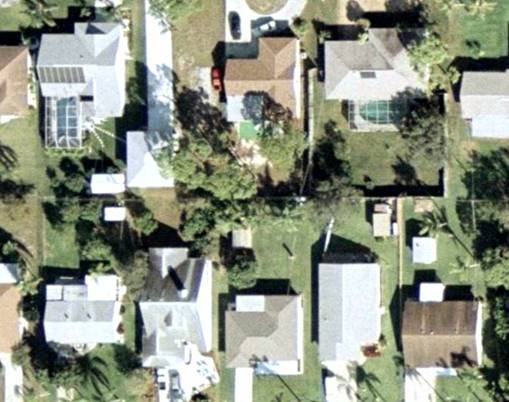
Figure 1.A residential area imaged in 2002 with film.
Collier County determined that they needed to create a 1-meter, high-altitude mosaic in true color as well as capture low-level imagery suitable for use in 1" = 100' (1:1200) mapping.For this part of the project, the county chose to use a Leica Geosystems' ADS40 digital sensor.The Collier County Appraiser's Office employed two consulting companies, 3001 Inc., a geomatics service company and North West Group, an aerial photography company, to provide them with orthophotography and photogrammetric mapping services in the past.With this project, they could compare the data between a digital sensor application and traditional film data capture at the same scale as the ADS40 flight.
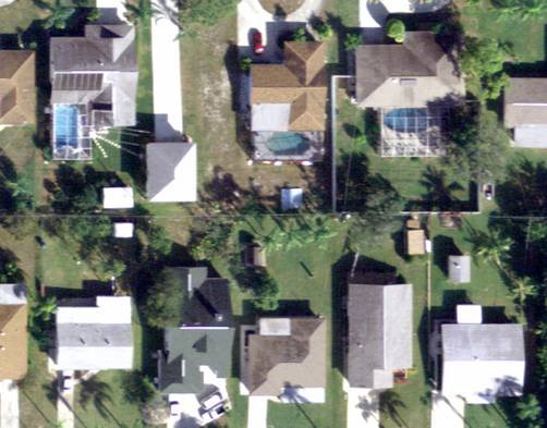
Figure 2.The same residential area imaged in 2003 with the ADS40
digital sensor.
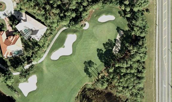
Figure 3.A golf course imaged in 2002 with film.
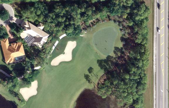
Figure 4.The same golf course imaged in 2003 with the ADS40
digital sensor.
Control Points, Digital Elevation, and Flight Lines
For ground processing of the flight mission, control points and a highly
accurate digital elevation model (DEM) from the first Collier County project
were used.The DEM for the urban area was a LIDAR-derived, 6-inch vertical
accuracy surface, ideal for the creation of high-resolution ortho-imagery.
This allowed for immediate rectification and enabled the team to compare
results visually and spectrally between film-based capture and the sensor.
The flight crew opted to fly North/South flight lines aligned with the image tiles of the final products.The flight lines passed though the center of each tile, allowing the flight team to cover an entire tile with one flight line, saving flight time and simplifying the mosaicking process. The flight plan was exported to its proprietary ACCUNAV Flight Management System (FMS), which enabled the team to navigate the plane accurately and efficiently along the appropriate flight lines.
Pushbroom Scanning Concept
The ADS40 captured a digital image one flight line at a time, continuously,
in a manner similar to the way a desktop scanner scans an image, a method
called pushbroom scanning or line scanning.Light entering the sensor lens
forms an image on a focal plane inside the sensor head.Linear CCD sensors
were positioned on the focal plate to capture light from only a portion
of that image, corresponding to a fixed angle in relation to the optical
axis of the lens, extending across the full width of the image.
A standard ADS40 configuration was comprised of ten linear sensors, each with 12,000 pixels.The three sensors that capture panchromatic (black and white) imagery were composed of pairs of 12,000 pixel arrays (for a total of 24,000), staggered from one another by half a pixel (3.25μm). These arrays were positioned at angles of 28o forward, 0o (nadir), and 14o backward.Three of the seven sensors were located behind a prism assembly, which split the light that would otherwise fall on a single sensor array.This light was then projected onto three sensor arrays corresponding to red, green and blue bands.The prism assembly was positioned at 16o forward; therefore this was the angle at which the true color imagery was captured.This method ensured perfect registration of the red, green and blue bands even before the imagery was rectified.The infrared band was captured with a single sensor positioned next to the nadir panchromatic arrays, at 2o backward.The design allowed for additional color channels to be added for multispectral imaging applications.
The three panchromatic channels guaranteed that all features on the ground were imaged three times at different stereo angles in a single continuous scan (figure 5).The completely overlapping coverage of the three panchromatic channels allowed for a very robust automatic aerial triangulation process to be performed by minimizing occluded areas and providing three different stereo angles (14, 28 and 42o).This was different than frame-based aerial photography, whether with film or digital framing cameras.With framing cameras, stereo imagery captured was generally captured by ensuring 60 percent forward overlap.This means that 50 percent of the terrain appears on three images.With the ADS40 all the terrain appears on the three panchromatic strips.
Figure 6.Overlapping coverage comparison between the ADS40 digital
sensor used in this project and a traditional film camera.
Because the digital sensor had a narrower field of view than typical film cameras, higher altitude flights were possible and building lean was minimized.During the Collier County flight mission, high-altitude data was captured from 20,000 feet above ground level (AGL) to provide the client with a well-balanced color image suitable for a county-wide mosaic at a 2.5-foot pixel resolution.Low-level flights were flown from 4,500 feet to provide 6-inch pixel imagery.
Flight Data Recording
The sensor was mounted in a Cessna Conquest twin engine turboprop aircraft.
Two mass memory units were available for the project.One unit was in flight
while the other downloaded data to the field processing computer and tape
backup.A single 540 GB mass memory unit held data for an entire flying
day (up to 12 hours of data acquisition), including imagery, GPS and IMU
data.Each flight line collected seven independent bands of image data
(forward, nadir and backward panchromatic; red, green and blue; near-infrared),
which totaled about 40 GB per hour of data acquisition in a 2.5:1 compressed
format.
After each flying day, the data was downloaded to a field computer (with 4 TB of RAID disk storage capacity) for initial data quality control.Because there was no film to send off for processing, the flight data was immediately available for review by the crew and the clients.If data was deemed unacceptable, reflights could occur while the flight team was still on site, eliminating the risk of data errors being discovered after the data was processed and after flight teams left the site.
The data storage and redundancy protocols were designed to require a minimum of two copies of the original data to be kept in different locations at all times.Therefore, the newly-acquired data was immediately archived twice to a portable tape robot using 100 GB LTO tapes (available soon in 200 GB capacity).One set of archives was kept in the field as backup data and one was sent to the office for immediate product generation.The goal was to deliver rectified imagery for large jobs starting two weeks after the first flight line is flown.Turnaround time depended on the size of the project area, but data was available for work and interpretation even before the flights were completed.
Instant Quality Assurance/Quality Control (QA/QC)
Because the completely digital data capture eliminated the need for
film processing and scanning, QA/QC could begin immediately upon flight
conclusion.When errors were found, reflights were performed immediately,
within the original flight frame.This eliminated costly delays and insured
that the flight would not be pushed out of the flying season.
Aerotriangulation
To perform automated softcopy aerotriangulation (AT), film images were
processed, scanned, imported and compressed to TIFF or JPEG files.Next,
stereo models were created and pass and tie points were measured.The measured
stereo models were then registered to ground control points to produce
a good AT solution.With softcopy frame imagery image points were selected
in multiple overlapping photographs using matching algorithms geared towards
frame aerial imagery, with a usual overlap of 60 percent.
The digital sensor provided a full 100 percent triple overlap.Thus, a multi-image matching approach was used, leading to minimal problems caused by occlusions, multiple solutions, image noise and surface discontinuities, which provided higher measurement accuracy through the intersection of more than two image rays.The known interior and exterior orientations were used to reinforce the geometric constraints and restrict the search space at known locations along the flight line.This rigorous measurement process was fully automatic (typically 80 to 90 percent success was achieved automatically).A human operator was required only for measuring ground control points, adding any control points needed for accuracy assurance and making manual measurements to strengthen any remaining problem areas due to image subject matter (shorelines, etc).The image points were then used in a bundle adjustment process that was very similar to that used in a conventional film-based workflow.ORIMA, Leica Geosystems' orientation management software was used to processes large data sets of image coordinates, ground control points and GPS coordinates, detect and eliminate blunders, and minimize remeasurement, was used in the workflow for both film and digital sensor data.The results were orientation/positional accuracies to the subpixel level without the time and cost required for the same process with film imagery.
Rectification of Imagery
The sensor enabled two different methods of creating 3D data.The first
method was traditional stereocompilation to capture feature and terrain
data.The second was the generation of digital terrain models using an
automated correlation process using information contained in the forward,
nadir and backward panchromatic channels.The software then created the
terrain surface through autocorrelation.
Next, the sensor could use the Level 1 data, which was planar rectified using the aircraft trajectory data, but not precisely georeferenced, to produce a DEM.The data was then able to be orthorectified and corrected for terrain displacement of features in the image using the DEM produced from the imagery.As an alternative, a DEM was produced from topographic LIDAR data.An available LIDAR DEM was used for the Collier County project.
Data capture for the low-level imagery in Collier County was completed in six days and the high-level flights were completed in two days.The imagery was rectified within four weeks and was reviewed for consistency.
"We refined this process in conjunction with 3001 and Leica Geosystems and set the target high.It was our desire to be able to turn around the product in under one week after acquisition date to allow us to deliver the final product to the client in less than two weeks," said John Welter, Vice President of North West Group.
The imagery from the sensor was delivered several times faster than could be accomplished with traditional film imaging.
16-Bit Data and 8-Bit Exports
The digital sensor captured data in a 12-bit dynamic range, which allowed
viewing of 4,096 gray levels per channel as opposed to 256 levels with
standard 8-bit imagery, such as most scanned film.The result was much
greater detail in areas of shadow and much clearer, crisper imagery.Other
dark areas, such as submerged vegetation, could also be more readily viewed
in this environment.The rectified images were stored in 16-bit TIFF format
for compatibility with image processing software.Since most image viewing
software available for end users could only handle imagery with 8 bits
per color (24 bits total for red, green and blue), the imagery needed to
be converted to 8-bit format.This process required some testing and a
special conversion method was developed by 3001 and North West Group for
the project.
Color Balancing and Mosaicking
Because the imagery required no chemical processing, the imagery yielded
very consistent tonal values.A dodging process was applied in order to
balance and stabilize brightness values relating to sun angle across the
image swath.Inherently, the scratches, dust and Newton ring artifacts
typically present in conventional film-based aerial photography processes
were not present.By designing a flight plan along the center lines of
the final tile scheme, the need to address and contend with image seams
was reduced and simplified.This flight plan yielded unequaled orthophotograph
quality.Upon completion of the orthorectification, the 16-bit sensor imagery
was converted to the more common 8-bit image color depth.Finally, a color-naturalizing
filter was applied to represent a final image that was more accurate and
pleasing to the human eye.The delivery image format was standard 8-bit
per color GeoTIFF, in addition to imagery compressed with MrSID (LizardTech)
for use on the Collier County Property Appraiser Web site (www.collierappraiser.com).
Using Digital Sensors with Remote Sensing
As with all forms of airborne imaging, reflected light was captured
from objects in the imaged area.Each object in the image reflected light
differently, producing a spectral signature in a continuous range of wavelengths.
Traditional film-based capture (color) was performed using emulsion layers
sensitive to bands of red, green and blue light.These bands overlapped
each other in color film data capture, and the result was a less distinct
spectral signature.
The digital sensor captured red, green and blue light in distinct bands with no overlap owing to the design of its color filters.It was therefore possible to calibrate the image to provide actual reflectance values of the ground surface.This calibration produced imagery in Collier County with much better definition than film-based data capture.Shadows and dark areas became much more visible on the imagery, allowing for better interpretation. With true reflectance values, it was possible to apply image interpretation methods to extract information about ground cover types and features that was not possible with traditional film data.As a result, the ADS40 lent itself to remote sensing applications far beyond that of standard film products.This spectral data could also be collected simultaneously with other sensor data, making it capable of operating as a remote sensing tool.
What Next?
3001 is already using LIDAR-derived DEMs (6-inch vertical accuracy)
with the digital sensor data.One future application of this system will
be the acquisition of LIDAR and digital imagery coincidentally."With the
ADS40 and the Leica ALS40 LIDAR scanner on board, we are capable of providing
customers with high-quality orthophotography in black and white, color
infrared, and true color, as well as LiDAR-derived DEMs in a fraction of
the time traditional techniques require," said Jay Arnold, Vice President
of GIS Services, 3001.
Better Than Film?
The ADS40 sensor has proven to be a versatile sensor, useful for a
variety of mapping applications.The combination of automation, multiple
product capture in one flight mission, the improved accuracies due to extreme
redundancy in the aerial triangulation process and reduced mosaicking are
difficult to ignore.Adding in the drastically decreased turnaround time
to product delivery makes it a very attractive proposition.Neither 3001
nor North West Group expect to see airborne digital sensors replace film
cameras for very high-resolution engineering mapping, but, for the majority
of county and statewide clients interested in data acquisition of larger
areas at 6-inch or lower resolution, it is an ideal alternative to film.
Aerial images courtesy of 3001, Inc and North West Group.