Autodesk OnSite 6 functions as a desktop GIS software product that can integrate, visualize, query and present spatial data. OnSite is only available through the Autodesk Map Series bundle as opposed to a stand-alone software package. Onsite comes with an easy to use graphical interface with menus, buttons and tools that are straightforward for a person with desktop GIS software experience. Common tools such as zooming in and out and measuring tools are easy to locate on the user interface. The Map Explorer on the left side of the application shows the layers and data sources that are displayed in the Map Window on the right. There is a status bar along the bottom where users can also set the scale of the map. (See Figure 1)

Figure 1
[Click for larger
image]
OnSite saves map files and associated layers in a Map Window File (.mwf) or as a Map Window XML File (.mwx) The Map Window files can be opened using OnSite or can be served in a webpage that uses Autodesk's Internet Mapping software called MapGuide.
Data Integration
Autodesk OnSite can
read the following vector formats directly: Autodesk OnSite and MapGuide
Spatial Data Files (SDF), AutoCAD DWG Files, Autodesk Map 5 Project Files,
Intergraph DGN, MapInfo Interchange (MIF/MID), ESRI ArcInfo coverages,
Oracle Spatial 8i and 9i spatial and locator, ESRI Shapefiles (SHP) and
data residing in ODBC and OLE/DB compliant data sources. OnSite also supports
data in AutoDesk DXF, ESRI Atlas BNA, and comma-separated values (CSV)
through the use of the SDF Loader.
Autodesk Onsite supports the following georeferenced raster formats: ECW, MrSID, GeoTIFF, TIFF with ESRI TIFF World Files, Band Interleaved by Line (BIL) with ESRI Image Integrator Files (HDR), and MapInfo Tab files. In addition, the software supports the following non-georeferenced formats: TIFF, TGA, CALS, PNG, BMP, and JPEG.
Map layers can be added to Onsite through the Insert menu or can simply be dragged and dropped from Windows Explorer. The vector and raster data are loaded in the Map Explorer as a map layer and displayed in the Map Window. Layers that have something in common can be bundled into layer groups to perform common operations on all layers in the group. Layers can also be static or dynamic to ensure that OnSite is displaying the most recent data. The Map Layer Properties allows users to change the name of the layer, link to secondary tables, change the style of the map features, and create themes based on the data associated with the layer. Attribute data for the Map Layer can be viewed by right clicking the layer and choosing Attribute Data Viewer from the menu or from the Layer menu.
Markups or redlines are separate layers in a map that can indicate areas that need to be changed on the map. Markup files are stored as an RML file and can be read by any application that supports RML files like Autodesk Map. Users can share their markup files with other users that are responsible for making changes to the drawings. For example, a manager could create a markup file in OnSite, send it to the person that digitizes maps to show area that need to digitized and edited in Autodesk Map.
Querying Capabilities
Onsite provides spatial
and attribute query wizards for users to ask questions of the data. Users
can specify which layers they want to be selectable through the “Make map
features selectable” checkbox in the layer's properties. There is a Select
button, Select by Polygon, and Select by Radius that allows the user to
select features directly on the Map Window. Selections can be cleared with
the Clear Selection button. Spatial queries among layers are limited in
the types of queries that can be performed. To perform a spatial query,
you can select features from a map layer, right click and choose Select
With, which prompts the user with a list of selectable layers to choose
the layer they want to select features from.
Features that are selected on the map are highlighted in the Map Window and the attributes can be viewed by opening the attribute data viewer and choosing Show Highlighted Records Only from the Highlight menu. Users can also open the Feature Properties dialog box that shows the attributes for one of the selected features at a time. The Zoom Go To Wizard finds features that match a query's criteria and allows the user to pick a feature from a list of values that matched the criteria (if there are multiple matches), and zooms in to that feature on the map display.
OnSite comes with a View Buffer command that is easy to use. The View Buffer dialog box will buffer a selected feature to the distance set in the dialog box and allows users to set the style of the buffer. If multiple features are selected, the user can buffer all features as one buffer or individual buffers for each selected feature. Buffers are stored in a buffer layer or in a layer that the user selects from the drop down menu.
Output Options
Printing presentation
quality maps is achieved in OnSite using the Page Setup and Print Preview
commands from the File menu. Onsite does not provide a separate window
for users to customize how they want to see their map layouts. The Page
Setup dialog box provides options for the user to create a Title for the
map, and checkboxes that will place a North Arrow, Legend, Scale Bar, Date
and Time, and File Path or URL on the map. There are also options that
allow the user to specify the Map Size and the Map Scale in the Page Setup
command. Once the user has specified their preferences in Page Setup, they
can preview the output with the Print Preview command. (See Figure 2) OnSite
generates a Layout based on the preferences set in the Page Setup. The
user has no control over the placement of the objects selected in the Page
Setup, Onsite places the Legend, North Arrow, etc. at predetermined locations
in the Print Preview window.
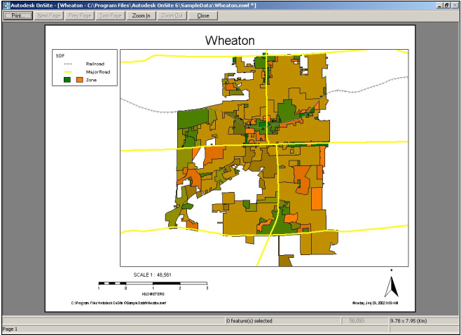
Figure 2
[Click for larger
image]
AutoDesk Raster Design 3
Autodesk Raster Design 3 converts scanner paper drawings, blue prints, aerial photographs, and paper maps into data that can be edited and managed in AutoCAD drawings. Raster Design functions within AutoDesk Map as a separate pull down menu called Image (See Figure 3) that contains functionality specific to raster imagery.
Raster Images
Raster images can be
inserted into an Autodesk Map drawing by selecting the Insert command from
the Image menu. Once an image is placed in a drawing, Autodesk Map creates
one instance of the image (called an insertion) in the drawing. If multiple
copies of an image are placed in a drawing, each copy is treated as a separate
insertion of the same image. The insertions can be managed using the Image
Manager dialog box and properties for individual insertions can be changed
without affecting other insertion of the same image.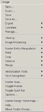
Each image has its own drawing properties that the user controls. The image properties can be accessed on AutoCAD’s Properties dialog box and specific properties include: Color, Linetype, Brightness, Contrast, Show Image, Show clipped image, Show non-ortho, and Transparency color.
Image Editing
Raster design provides
the following tools for image editing:
- Correlating: Correlating refers to the process of positioning an image within the AutoCAD coordinate system so the scale, rotation, and coordinates match AutoCAD’s units and coordinates. Raster Design has several commands that can be used to correlate images including Match, Scale, Displace and Rubbersheeting.
- Rubbersheeting an Image after Correlation: Rubbersheeting works by transforming an image so that the points you specify in the image match corresponding points in the drawing as closely as possible. The Triangular method uses control points entered by the user to triangulate the image, and then performs a series of small transformations on those triangular areas. The Polynomial method uses control points specified by the user and then performs a single transformation on the entire image.
- Histogram Editing Filters: The Raster Design Histogram is a set of multi-purpose editing filters you can use to permanently change the appearance of grayscale and color images. The Histogram dialog box allows the user to adjust the brightness of an image, maximize image detail, convert color and grayscale images to binary images, convert color images to grayscale, and adjust the contrast in a non-linear fashion.
- Image Processing and Cleanup: There are several other Image Processing and Cleanup commands that can permanently edit images: Invert, Despeckle, Color Depth, Convolve and Mirror.
- Rubbing and Cropping: Rubbing and cropping remove selected areas of binary, grayscale and color images. A Rub changes the removed pixels to the current transparent color that is set for the image. A Crop deletes pixel data outside the selected boundary area.
- Merging Images: Two or more images can be merged to reduce the number of images that are archived with the project. The merged image will take on the properties of the destination image and any area within the extent of both images that has doesn't have a portion of either raster image will be filled with the transparency color.
Converting Raster
to Vector
Raster Design comes
with a set of tools for Vectorizing Raster Data and Text Recognition to
convert features on the image to vector data and text. Data can be
vectorized from the raster image with one of the following vectorization
tools: line, polyline, rectangle, circle, arc, and text, and then using
the tool to trace over the raster feature. Autodesk Map snaps the cursor
to a feature when it's near a raster feature that can be vectorized. Once
the user traces the appropriate feature, they press Enter to convert the
raster feature to a vector feature.
Raster Design has three follower tools that provide a semi-automatic method of tracing raster geometry. The three tools are the Polyline Follower, Contour Follower and the 3D Polyline Follower. The follower tools are listed on the Image menu under Vectorization Tools. To start the Polyline Follower tool, the user can click on a line segment on the raster image. The Polyline Follower tool will snap to a raster feature and automatically follows the selected polyline until it cannot proceed on its own and needs input from the user, such as at a raster endpoint or an intersection. The follower tool speeds up the digitization of lines and curves by automatically generating the lines based on what is shown on the raster image.
Raster Map also includes text recognition commands to convert raster text to AutoCad Text or Mtext. The Text Recognition dialog box has three main sections: Input, AutoCAD Output, and Verification Display. Once a block of raster text is selected, the Verify Text dialog box appears with the raster text in the top window and the recognized text is displayed in the lower window. The recognized text can be edited in the lower window and Raster Design will highlight any text that is misspelled. Users should verify that the text from the Optical Character Recognition matches the text on the raster image.
Integrated Workflows
The MapSeries Product
from Autodesk is designed to be a complete solution for all of a user's
mapping needs. The manual for OnSite provides several examples to streamline
the workflows with the three products. Quality assurance users can redline
areas that need changes in OnSite and send an RML file to a drafter using
Autodesk Map to apply the changes. The drafter may even need to use Raster
Design to digitize the areas from a raster image that need corrections.
Another example would be to update parcel maps and publish those on the
Internet. This workflow would be accomplished by updating parcel drawings
in Autodesk Map, opening the drawing in Onsite and saving it as an Map
Window File (.mwf) that can be served over the Internet using Autodesk's
MapGuide (sold separately).
Conclusion
Autodesk Map Series
delivers a complete solution for data editing to raster image capabilities
to desktop mapping with its three products in Map Series. The only area
of concern that I have is for GIS users that do not have a need for the
heavyweight editing capabilities that Autodesk Map delivers, cannot purchase
the desktop product, OnSite, as a standalone product at this time. For
CAD users that need GIS functionality, Autodesk Map Series is a complete
set of GIS tools that complements the functionality of AutoCAD.