System Requirements
Operating System: Windows® NT 4.0 with SP 5.0 or later, Windows 98, Windows Millennium Edition (ME), Windows 2000, Windows XP
Processor: Pentium 233 (minimum), Pentium 450 or higher (recommended)
RAM: 32 MB (minimum), 64 MB (recommended)
Video: 800 x 600
VGA with 256 colors (minimum), 1024 x 768 SVGA with 64K
colors (recommended)
Hard Disk:
- 140 MB (minimum) on the drive where Autodesk Map will be installed
- 64 MB of available swap space for optimal performance
- 150 MB (minimum) – 170 MB (recommended) on the drive that contains the system folder
- 20 MB for share files (by default located at Program FilesCommon FilesAutodesk Shared)
The Autodesk Map Series is a complete solution for all of a user's mapping needs that consists of three bundled software products: Autodesk Map™ 5, Autodesk® Raster Design 3 and Autodesk OnSite® 6 plus all the extensions for Autodesk Map 5 and AutoCAD® 2002. Actually users get four products as Autodesk Map 5 is built on the foundation of AutoCAD 2002 and contains all the functionality of AutoCAD 2002 as well as its own mapping tools. Autodesk Map 5 is used to create, maintain, analyze and produce mapping information in a CAD environment. Autodesk Raster Design 3 converts scanned paper drawings, blueprints, and aerial photographs into maps that can be managed and edited in AutoCAD drawings. Autodesk OnSite makes it easy to integrate many different data types, visualize, query and create presentation quality prints.
For the purpose of this review I will review the functionality of Autodesk Map 5. In next month's review I will review the functionality in Autodesk Raster Design 3 and Autodesk OnSite 6. The three products in the Autodesk Map Series are designed to work together in an integrated workflow. Autodesk Map and Raster Design can be purchased separately, while OnSite can only be purchased as a component in the Map Series product suite.
Installation
AutoDesk Map Series comes with three CD’s. The first CD has the program installation files, the second CD has sample data and Extensions and the third CD has a learning assistance on it. The installation process is pretty straightforward on the program installation CD. Users that are installing on Windows NT, Windows 2000 or Windows XP must have Administrator or Power User permissions to install the software.
Once the installation starts the user has the option for a single-user installation or a Network installation. The user also has the option to choose which software applications from Map Series. Autodesk has replaced its previous hardware locking system with a software license management system that makes the software more reliable and easier to install and maintain.
Upon completion of the installation, the user has to reboot their system before they can begin running the Map Series software. When I started Autodesk Map I was also asked to register the software via the Internet, fax, email or mail. Users have a 15-day grace period in which to register the software. I chose to register via the Internet and received a response with the confirmation code instantaneously on my screen along with a confirmation email.
Autodesk Map 5
The user interface for Autodesk Map 5 and the Map menu options is shown below:
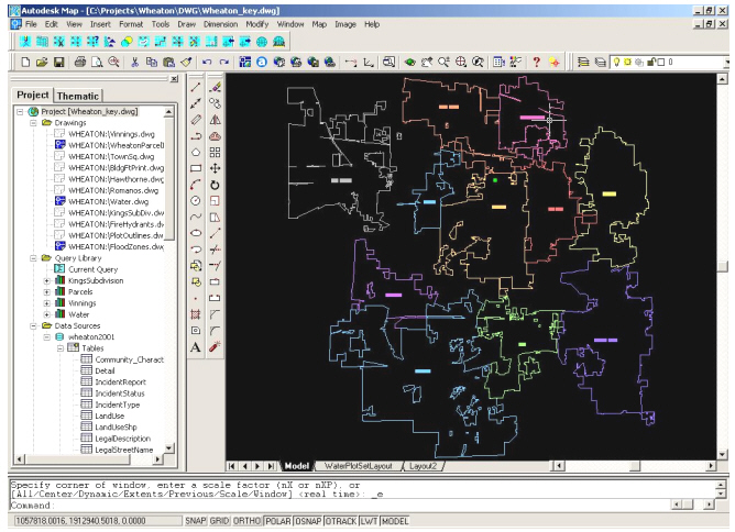
FIGURE 1.
The pulldown menus across the top contain standard Autocad menus along with a Map menu for mapping capabilities and an Image menu for the Raster Design functionality. The window to the left is the Project Workspace which displays all the data you are working with: Drawings, Query Library, Data Sources, Topologies and Link Templates. The Project Workspace also has a Thematic Tab which stores the symbology of a theme. The window on the right displays the drawings and queries specified in the Project Workspace in the Model and Layout tabs. The Model tab is where you spend most of your time creating and editing your drawing. The Layout tabs are where you can also view and edit paper space objects, such as title blocks. On the bottom of the screen is a command line window that shows the status of a command being performed, tracks the history of commands, and allows users to enter commands manually for the software to perform.
Thematic Mapping Capabilities
Thematic maps of drawings or queries can be generated by clicking on the Thematic tab in the Project Workspace. To add a theme, you can right click in the area below the thematic tab and select “Add New Theme”, which starts a Thematic Wizard. Step one of the wizard will ask you to choose the drawing or query, select the type of theme and the thematic values. Step two asks you how to display the values and a theme description. In Step three you can specify labels for the values in the theme and select color ramps or individual colors for the values. Lastly, Step four asks you for a title for the theme. The finished theme and the legend are then placed under the Thematic tab. Users can go back and modify any theme elements such as individual theme colors, color ramp, or the value label.
Coordinate Systems
The software includes a number of pre-defined coordinate systems and the ability to define custom coordinate systems. Performing a coordinate system transformation within Autodesk Map is fairly easy. The user needs to right click on the Project's name at the top of the Project Workspace and select coordinate system from the popup menu. There will be a description of the current coordinate system and a button to change the coordinate system. You will then be asked for a Category and a Coordinate System within that Category to make the change. The software changes the coordinate system on the fly in the Model space.
Importing and Exporting Data
Autodesk Map 5 provides Import capabilities to import data from other CAD and GIS systems, and supports most common image file formats. The software allows users to import data from the following GIS formats: Autodesk MapGuide files, ESRI’s Arc/Info Coverages, ESRI’s Arc/Info Export files, ESRI’s ArcView Shapefiles, Intergraph/Microstation Design files and MapInfo MIF files. I imported a shapefile and an Arc/Info coverage into the Model tab. At first, I didn't set the coordinate system for the project so the map files were randomly placed in the Model space. I went back and set the coordinate system of the project before importing the files and the files matched up correctly to each other after the import. The files were drawn on the map as white lines in the Model space, but I was not sure if the imported layers could be turned on and off. I did try to create a thematic legend for the imported layers, but could not figure out if there was a way to display the information better than simple white lines.
You can also export data from Autodesk Map into the same GIS formats listed above. Depending on the type of file you choose to export to, Autodesk Map will prompt you for information about the data you wish to export. For example, if you want to export to a shapefile, it will ask what type of entity to export (point, line, polygon, or text), coordinate information, select objects manually or automatically, and to include the table data with the export. After exporting a couple of files, I opened an exported shapefile and coverage in ArcView and the data was georeferenced perfectly.
Working with Databases
Autodesk Map also allows the user to connect to ODBC compliant databases and will create a DSN automatically when the users connects to dBase 3 and 5, Microsoft Excel 97, Paradox 7.0 and Microsoft Visual FoxPro 5.0. For other ODBC compliant databases, such as Oracle 7.3 and 8.0 or SQL Server 6.5, the user will need to create the DSN and enter the settings manually before using they can connect. By default, Autodesk Map connects to Microsoft Access 97 using the Jet provider and does not require a DSN. Users can connect to a database by double clicking on the Data Sources item in the Project Workspace. Autodesk Map will add all the tables from the database to the Project Workspace and users can view the data in the tables by double clicking on the table name. Once the tables are attached, the user can link records from the database table to objects in the drawings. The Link Templates in the Project Workspace defines how databases are connected to objects within the drawing files.
AutoDesk Map 5 supports Oracle Spatial so users can store their drawings in an Oracle database. The Oracle spatial database stores the drawing objects as individual records in the database. Attribute data, object data, or linked templates associated with the objects are stored in separate tables. The Map pulldown menu has separate menu item for Oracle Spatial that allows the user to Connect/Disconnect to Oracle, Import/Export to Oracle, Update Selected Objects/Erase Objects in Oracle, and Spatial Indexing.
Editing Tools
Autodesk Map provides the following
tools for cleaning up drawing that are digitized, imported from other file
formats, or derived from inaccurately drawn maps:
- Delete Duplicate Objects
- Erase Short Objects
- Break Crossing Lines
- Extend Undershoots
- Erase Dangling Objects
- Simplify Linear Objects
- Correcting Nodes
- Snap Cluster Nodes
- Dissolve Pseudo Nodes
- Edge Matching
In addition, the following are
a list of editing tools available with Autodesk Map:
- Moving, Rotating and Scaling Objects
- Defining Text Insertion Points
- Filling Polygons
- Rubber Sheeting
- Breaking Objects into Map Boundaries
- Trimming Objects Using a Closed Boundary
- Creating Closed Polylines from a Topology
Building Nodes and Polygon
Topology
With Autodesk Map, a user can organize
graphical and textual data in three types of topologies: node, network,
and polygon, and use these topologies to perform spatial analysis, including
network tracing, shortest-path routing, polygon overlays, and polygon buffer
generation. Autodesk map has a topology administration and editing tools
that allows you to:
- Load and unload topology from memory
- Delete and rename a topology
- Add a link or node to a topology
- Audit the geometry of a topology
- Complete and recreate a topology
- Edit part of a topology
- Determine statistics for a topology.
The topology commands are located
on the Map menu and the topology administration can be found on the Topology
item in the Project Workspace.
Sharing Files among Users
Autodesk Map allows users to set drive aliases that allows different users that work with the same project to locate drawings. Multiple users in a network environment are able to share drawings and edit different objects in the drawing at the same time. Autodesk Map includes an internal locking mechanism that controls access and object editing by users to open drawing files and source files attached to open projects. Redline Markup Files (.rml) can be created by any user with text and graphics to show specific areas of interest. For example, a person could create a redline in Autodesk OnSite to show a subordinate an area on a drawing where changes need to be applied. The subordinate can import the redlines into Autodesk Map to view the areas that need to be updated.
Conclusion
Autodesk Map 5 is designed to be a heavyweight data creation and editing software package. The software is built with all the functionality of AutoCAD within the product so that users can spatially enable their drawings to be used with their GIS data. In the next part of the software review on Autodesk Map Series, I will look at Autodesk Raster Design and Autodesk OnSite and will discuss the integrated workflow between the three products in the product suite.
Review courtesy of:
![]()